Model Tree
Properties of elements
Select a node or element to view its properties
Select a node or element to view its properties
Name: Not selected
Type:
Standard:
Modulus of elasticity (E):
Density (ρ):
Poisson's ratio (ν):

Type: Not selected
Section: Not selected
Standard: Not selected
Cross-sectional area (A): —
Moment of inertia (I11): —
Moment of inertia (I22): —
Height (H): —
Width (B): —
Web thickness (tw): —
Flange thickness (tf): —
Centroid (c11): —
Centroid (c22): —
RodX is an intuitive, browser-based tool for fast and clear structural analysis in 2D. It allows you to build models directly on the canvas, apply loads, define supports, and evaluate the structural response with a single click. RodX focuses on simplicity, clarity, and speed. You do not need to install software or write scripts — everything works directly in your browser. The platform performs linear elastic analysis using established finite element methods and returns results instantly.
The version of RodX supports:
RodX is designed for both students and practicing engineers: you can draw quickly, experiment with structural behavior, and gain immediate insight into how loads are distributed across the structure.
If you are opening RodX for the first time, the following sections will guide you through the interface, the modeling workflow, how to set up loads, how to run an analysis, and how to interpret the results.
The canvas is the main working area where you draw and edit your structural model.
Here you can:
Most interactions happen directly on the canvas using both mouse buttons and keyboard. For example you can use Ctrl+left mouse button to select multiple elements.

Right-click anywhere on the canvas to open the context menu.
This menu changes depending on what you click:
The context menu is the fastest way to work in RodX.
The Model Tree displays the structure of your project in a hierarchical list.
It contains:
You can expand/collapse categories and click any item to select and edit it.
The Model Tree provides a clear overview of your model and is useful for managing large projects.

When you select any object (node, rod), its attributes appear in the Properties Panel.
From here you can edit:
All model parameters are editable through this panel.
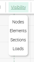
The toolbar contains essential tools and display options:
The toolbar provides quick access to commonly used features while keeping the interface clean.
At the bottom of the screen, the status bar shows:
This helps keep track of what you’re doing at any moment.
RodX is optimized for fast modeling using of mouse:
Nodes are the fundamental points of the model. They define geometry and connect structural elements.
You can:
Nodes also serve as:
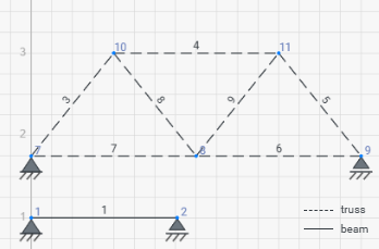
RodX supports two types of 1D elements:
Beam Element
A beam element resists:
For beam elements, shear deformations are not considered at this stage.
Truss Element
A truss element carries only axial force (tension/compression). It has no bending stiffness.
You can:
The beta angle rotates the element’s local coordinate system. It is measured in degrees, counterclockwise, and is useful when:
If no rotation is needed, leave beta = 0°.
Every element must have a material that defines:
RodX includes a library of standard steel grades (EU/US), and you can define custom materials.
Material assignments happen manually via the Properties Panel. Add materials to the model before assigning it to the rod.
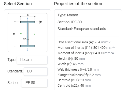
Sections define the geometric properties of an element:
RodX includes:
Assign a section by:
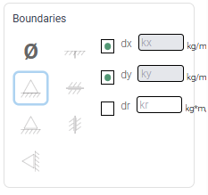
You can define supports with arbitrary restraint patterns for dx, dy, and dr.
Common presets include:
These are simply predefined combinations; you may adjust DOF manually for custom conditions.
Creating, editing, and removing a hinge is done through the context menu (right-click on a node or an element end).
Elastic restraints provide spring stiffness in any DOF:
Useful for soil springs, flexible bearings, or partially restrained connections.
Creating, editing, and removing elastic support is done through the properties panel.
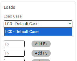
Node loads are applied at the Properties Panel.
Supported types:
Node loads belong to a specific load case selected during assignment. A load can be reassigned to a different load case at any time through the Load Cases window. By default, all newly created loads are placed into LC0 – Default Case, unless another load case is selected.
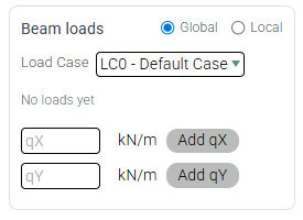
Element loads act along the length of a beam element.
RodX supports:
Loads are defined and deleted via the Properties Panel.
If enabled, self-weight is generated automatically from:
Self-weight is applied as an element load via Load Cases window.
Load cases group loads into independent scenarios that are analyzed separately.
Key points:
Load combinations are linear combinations of load cases with user-defined factors.
Features:
Load combinations can be created at any time, even before running the analysis. They become available for result visualization once all load cases included in the combination have been analyzed.
RodX stores models locally as JSON files. Saving and opening models are handled entirely on the user’s device.
The Export function saves the current model to a *.json file.
Key points:
The file can later be opened in any browser session to restore the model.
The Import function loads a previously saved *.json model.
Notes:
RodX supports importing geometry from DXF files for faster model creation.
Imported entities:
After import, the user can adjust materials, sections, supports, and loads as needed.
The Results button becomes available once the analysis has been completed. Any change to the model — except creating load combinations, adding canvas notes, or modifying units — disables the Results button and requires recalculation.
In the Results view you can review:
Fiber stresses reflect the section’s beta-angle (local rotation of the cross-section). Results always correspond to the active load case or load combination.
All elements, nodes, loads, and supports will be deleted from the model.
Materials and sections will not be deleted.
One or more elements are missing material or section properties. Please assign them before running the analysis.
The geometry of the structure is imported using the current units of measurement set in the model. Make sure the model units match the units used in the DXF file (e.g., mm or m) before importing.
Your structural analysis has been completed successfully. You can now view the results.
RodX is optimized for desktop browsers to provide the best experience for structural analysis. Mobile and tablet versions are currently in development.
For now, please visit rodxcalc.com on your desktop or laptop computer.
We will announce the mobile release soon!