Case 01 — Axial bar under concentrated loads
This verification case examines the axial displacement of a prismatic steel bar subjected to multiple concentrated axial forces. The results obtained with RodX are verified against analytical solutions and industry-recognized finite element analysis (FEA) software.
Description
A steel bar of diameter 50 mm is subjected to the axial loading shown in the figure. The bar is fixed at point A and loaded by concentrated forces applied at nodes B, C, and D along its length.
Determine:
- The axial displacement at point D
- The displacement of point B relative to point C
Structural scheme
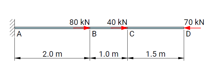
Geometry, boundary conditions, and load applications used in the verification model.
Model parameters
| Parameter | Value |
|---|---|
| Element type | Beam element |
| Material | Steel |
| Young's modulus | 2.0 × 10⁸ kN/m² |
| Diameter | 0.05 m |
| Boundary conditions | Fixed at point A |
| Loads | Concentrated axial forces |
Numerical results
Displacements

Axial Force

Table results from RodX

Comparison
| Node | Analytical solution | RodX | Midas/Civil |
|---|---|---|---|
| Δx(D) | -0.0891 | -0.0891 | -0.0891 |
| Δx(B-C) | -0.0764 | -0.0764 | -0.0764 |
The numerical results obtained with RodX are in agreement with the analytical solution and reference FEA results.
Reference
- Hibbeler, R. C. Mechanics of Materials, 10th Edition (SI Units), Pearson Education, 2017, Example 4.1, p. 147.