
Verification & Benchmarks

These verification cases demonstrate the accuracy of RodX calculations by comparing results against analytical solutions, classical benchmark problems, and industry-recognized FEA software. This section presents a structured set of verification cases used to validate the RodX 2D finite element solver.

Verification methodology

The objective of the verification process is to ensure the reliability of results produced by the computational solver and by the RodX interpretation layer for all element types and boundary conditions available in the platform.

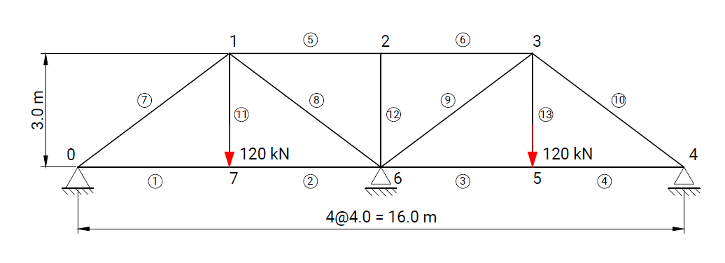
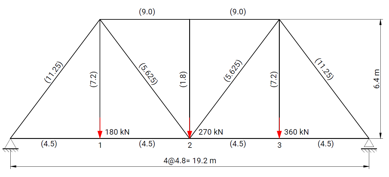
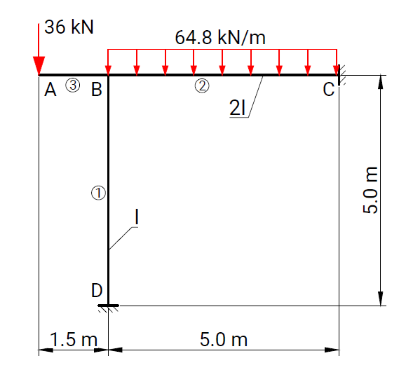
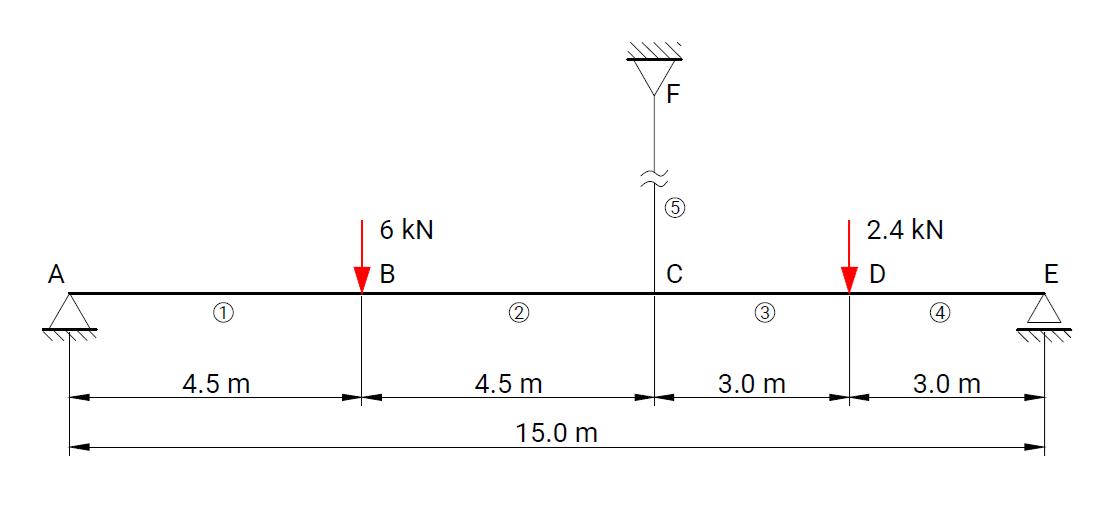
Each verification case is based on a well-defined structural scheme taken from widely recognized and authoritative textbooks on structural analysis and strength of materials. The presented problems cover the full range of supported modeling features, including beam and truss elements, hinges, elastic supports, and various boundary condition configurations.

For each case, numerical results obtained with RodX are compared not only with analytical solutions, but also with results from equivalent models solved using industry-recognized finite element analysis (FEA) software. The comparison includes nodal displacements, internal forces, reaction forces, and the qualitative shape of force diagrams. Differences in the orientation of bending moment and shear force diagrams may occur and are attributed to variations in sign convention.

Axial bar verification cases

Axially loaded bar fixed at one end with concentrated forces applied at intermediate nodes

Case 01 — Axial bar under multiple concentrated loads

Verification of axial displacements for a prismatic steel bar subjected to multiple concentrated axial forces. The bar is fixed at one end and loaded at intermediate nodes along its length. Numerical results obtained with RodX are compared with analytical solutions and results from industry-recognized FEA software.

  • Structure: Axial bar
  • Element type: Beam element (axial response)
  • Static determinacy: Statically determinate
  • Boundary conditions: Fixed support
  • Loads: Concentrated axial forces
Rigid beam supported by elastic vertical posts with different stiffness

Case 02 — Rigid beam supported by elastic vertical posts

Verification of vertical displacement of a rigid beam supported by two vertical elastic posts with different stiffness. The system consists of a rigid horizontal beam resting on steel and aluminum posts and subjected to a concentrated vertical load. This verification case validates the correct implementation of axial bar elements with different material stiffness and their interaction with a rigid beam element in the RodX finite element solver.

  • Structure: Rigid beam with elastic supports
  • Element type: Beam element
  • Static determinacy: Statically indeterminate
  • Boundary conditions: Fixed supports at posts
  • Loads: Concentrated vertical load

Beam verification cases

Steel beam on elastic supports under concentrated vertical load

Case 03 — Beam on elastic supports under concentrated load

Verification of vertical displacement of a steel beam supported by two identical vertical elastic springs. A concentrated vertical load is applied at an intermediate node along the beam span. This verification case validates the correct implementation of vertical elastic supports (spring elements) and their interaction with beam elements in the RodX finite.

  • Structure: Beam on elastic supports
  • Element type: Beam element
  • Static determinacy: Statically indeterminate
  • Boundary conditions: Vertical elastic supports (springs)
  • Loads: Concentrated vertical load
Cantilever beam with rotational spring support under concentrated load

Case 09 — Cantilever beam with rotational spring under tip load

A cantilever beam of finite length is subjected to a concentrated vertical load applied at its free end. The fixed end of the beam is supported by a rotational spring with a specified rotational stiffness. Vertical displacement and rotation at the free end are evaluated. This verification case validates the correct implementation of rotational spring supports and their influence on displacements and rotations in beam elements.

  • Structure: Cantilever beam with rotational spring
  • Element type: Beam element
  • Static determinacy: Statically indeterminate
  • Boundary conditions: Translational restraints with rotational spring at fixed end
  • Loads: Concentrated vertical nodal load

Truss verification cases

Symmetrical planar truss under vertical loading

Case 04 — Symmetrical truss under vertical loading

A symmetrical planar truss structure is subjected to vertical loads applied at selected joints. The structure is supported at both ends and modeled using truss elements only. This verification case validates the correct calculation of internal axial forces in truss elements subjected to symmetrical vertical loading.

  • Structure: Planar truss
  • Element type: Truss element
  • Static determinacy: Statically determinate
  • Boundary conditions: Pinned supports
  • Loads: Vertical nodal forces
Planar truss with joint displacements under vertical loading

Case 05 — Truss joint displacements under vertical loading

A planar truss structure is subjected to multiple vertical loads applied at intermediate joints. The geometry of the truss and cross-sectional areas of the members are defined as shown in the reference scheme. The horizontal and vertical displacements of joint L3 are evaluated. This verification case validates the accuracy of nodal displacement calculations in truss elements, including both horizontal and vertical displacements of joints.

  • Structure: Planar truss
  • Element type: Truss element
  • Static determinacy: Statically determinate
  • Boundary conditions: Left support fixed in Ux and Uy, right support fixed in Uy
  • Loads: Concentrated vertical nodal loads

Frame verification cases

Rigid planar frame under combined concentrated and distributed loading

Case 06 — Rigid frame under combined loading

A rigid planar frame is subjected to a concentrated vertical load applied at joint A and a uniformly distributed load acting along the horizontal beam. The frame consists of a vertical column and a horizontal beam with different flexural stiffness. Bending moments at selected sections of the frame are evaluated. This verification case validates the calculation of bending moments in frame elements subjected to combined concentrated and distributed loading.

  • Structure: Planar rigid frame
  • Element type: Beam element
  • Static determinacy: Statically indeterminate
  • Boundary conditions: Fixed supports
  • Loads: Concentrated nodal load and uniformly distributed load
Composite beam with hanger rod under vertical concentrated loads

Case 07 — Composite beam with hanger rod under vertical loads

A timber beam is supported at both ends and subjected to two vertical concentrated loads. At an intermediate point, the beam is connected to a vertical steel hanger rod anchored to an overhead support. The vertical displacement of the connection point, support reactions, and axial force in the hanger are evaluated. This verification case validates the interaction between beam and truss elements in a composite structural system, including the correct calculation of displacements, support reactions, and axial force in a hanger rod.

  • Structure: Composite beam-hanger system
  • Element type: Beam element, truss element
  • Static determinacy: Statically indeterminate
  • Boundary conditions: Pinned support at A, roller support at E, pinned support at F
  • Loads: Concentrated vertical nodal loads
Planar frame under nodal and distributed vertical loads with internal hinges

Case 08 — Planar frame under nodal and distributed vertical loads

A two-dimensional frame structure is subjected to vertical static loads, including concentrated nodal forces and a uniformly distributed load. The frame consists of two vertical columns connected by a horizontal beam and includes pinned connections at intermediate nodes. Shear force and bending moment diagrams are evaluated for two independent load cases. This verification case validates the correct modeling of internal hinges in frame elements and their influence on shear force and bending moment distributions.

  • Structure: Planar frame
  • Element type: Beam element
  • Static determinacy: Statically indeterminate
  • Boundary conditions: Fixed supports at base nodes, pinned internal connections
  • Loads: Concentrated nodal loads and uniformly distributed loads