Case 05 — Statically Determinate Truss Under Concentrated Loads
A planar truss structure is subjected to multiple vertical loads applied at intermediate joints. The geometry of the truss and cross-sectional areas of the members are defined as shown in the reference scheme. The horizontal and vertical displacements of joint L3 are evaluated. This verification case validates the accuracy of nodal displacement calculations in truss elements, including both horizontal and vertical displacements of joints.
Description
Consider the truss shown in the figure, which is subjected to vertical loads of 180 kN, 270 kN, and 360 kN at joints L₁, L₂, L₃ respectively. The geometry of the truss, including all member lengths, is indicated in the figure. The cross-sectional areas of the members (given in parentheses) are expressed in units of 10⁻³ m².
Determine:
- Horizontal and vertical deflections of joint L₃ caused by the applied loads.
Structural scheme
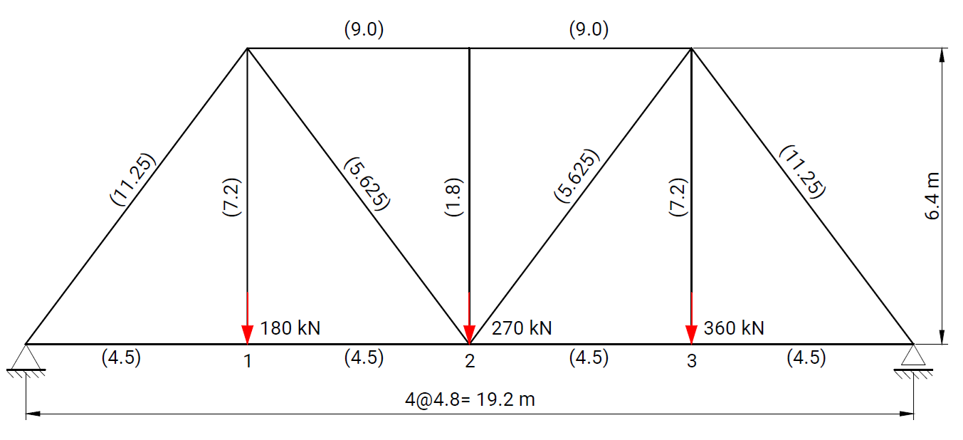
Geometry, boundary conditions, and load applications used in the verification model.
Model parameters
| Parameter | Value |
|---|---|
| Element type | Truss element |
| Material | Steel, 2.0 × 10⁸ kN/m² |
| Section properties | A = various |
| Boundary conditions | Left node: Ux, Uy restrained; Right node: Uy restrained |
| Loads | Concentrated loads −180 kN, −270 kN, and −360 kN applied at nodes 1, 2, and 3 respectively in the Y direction |
Numerical results
Displacements

Axial force distribution

Table results from RodX

Comparison (mm)
| Parameter | Analytical solution | RodX | Midas/Civil |
|---|---|---|---|
| Δx(3) | 4.68 | 4.68 | 4.68 |
| Δy(3) | -7.60 | -7.60 | -7.60 |
The numerical results obtained with RodX are in agreement with the analytical solution and reference FEA results.
Reference
- C.K. Wang, Intermediate Structural Analysis, McGraw-Hill, 1985, p. 80.