Case 06 — Rigid frame with combined concentrated and distributed loads
A rigid planar frame is subjected to a concentrated vertical load applied at joint A and a uniformly distributed load acting along the horizontal beam. The frame consists of a vertical column and a horizontal beam with different flexural stiffness. Bending moments at selected sections of the frame are evaluated. This verification case validates the calculation of bending moments in frame elements subjected to combined concentrated and distributed loading.
Description
Analyze the rigid frame shown in the figure. The frame is subjected to a concentrated load of 36 kN applied at joint A, a uniformly distributed load of 64.8 kN/m along the horizontal member BC, and has member lengths and stiffnesses as indicated (the horizontal beam has flexural rigidity 2I and the vertical column has I).
Determine:
- Bending moments
Structural scheme
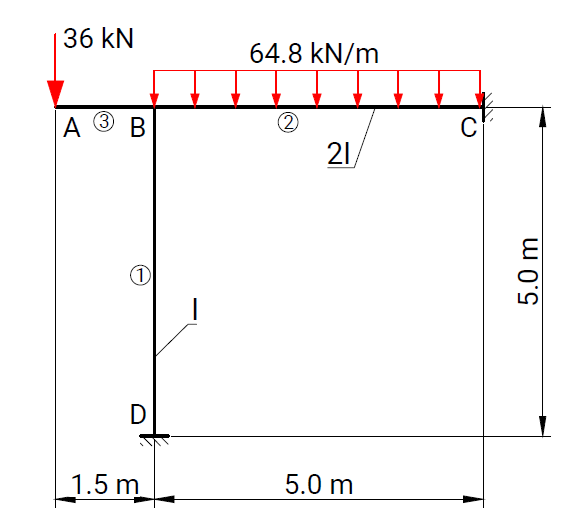
Geometry, boundary conditions, and load applications used in the verification model.
Model parameters
| Parameter | Value |
|---|---|
| Element type | Beam element |
| Material | Steel, 2.0 × 10⁸ kN/m² |
| Section properties | I = 8×10⁻⁶ m⁴, I = 16×10⁻⁶ m⁴ |
| Boundary conditions | Nodes D, C: fixed |
| Loads | Concentrated load −36 kN at node A; Uniformly distributed load −64.8 kN/m on rod BC |
Numerical results
Displacements

Bending moment diagram

Table results from RodX

Comparison (kN·m)
| Section | Analytical solution | RodX | Midas/Civil |
|---|---|---|---|
| A(3) | 0.0 | 0.0 | 0.0 |
| B(3) | 54.0 | -54.0 | -54.0 |
| B(2) | 81.0 | -80.9 | -80.9 |
| C(2) | 162.0 | -162.2 | -162.2 |
| B(1) | 27.0 | -26.9 | 26.9 |
| D(1) | 13.5 | 13.44 | -13.44 |
The numerical results obtained with RodX differ from the analytical solution by less than 1% and fully agree with the reference FEA results. Differences in the sign of bending moment values are due to the use of different sign conventions.
Reference
- C.K. Wang, Intermediate Structural Analysis, McGraw-Hill, 1985, p. 205.