Case 08 — Portal frame with internal hinge under multiple load cases
A two-dimensional frame structure is subjected to vertical static loads, including concentrated nodal forces and a uniformly distributed load. The frame consists of two vertical columns connected by a horizontal beam and includes pinned connections at intermediate nodes. Shear force and bending moment diagrams are evaluated for two independent load cases. This verification case validates the correct modeling of internal hinges in frame elements and their influence on shear force and bending moment distributions.
Description
A 2-D frame structure is subjected to vertical static loads, including both concentrated forces and a uniformly distributed load. The geometry and support conditions of the frame are shown in the figure. The frame has two vertical columns of height 10 ft, spaced 18 ft apart, and includes a pinned connection at nodes 2, 4, and 6.
Determine:
- The shear force diagram
- The support reactions at A and E
- The bending moment diagram
Structural scheme
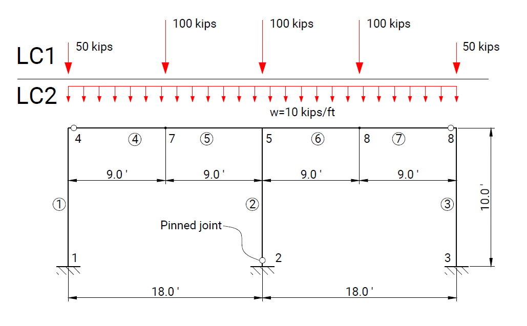
Geometry, boundary conditions, and load applications used in the verification model.
Model parameters
| Parameter | Value |
|---|---|
| Element type | Beam element |
| Material | Steel, 30 000 ksi |
| Section properties | Columns: A = 10 000 000 in², I = 13 824 in⁴; Beams: I = 27 000 in⁴ |
| Boundary conditions | Nodes 1, 3 – fixed; Node 2 – pinned; Nodes 4, 8 – beam end releases for rods 4 and 7 |
| Load Case 1 | Nodal load −50 kips at nodes 4, 8 and −100 kips at nodes 5, 6, 7 |
| Load Case 2 | Uniformly distributed load −1 kips/ft for rods 4, 5, 6, 7 |
Numerical results
Load Case 1: Shear Force and Bending Moment Diagrams


Load Case 2: Shear Force and Bending Moment Diagrams


Comparison for Load Case 1
| x/L (rod) | Analytical solution | RodX | Midas/Civil |
|---|---|---|---|
| BM (4-5) 0.00 | 0.00 | 0.00 | 0.00 |
| 0.25 | 1687.50 | 1687.50 | 1687.50 |
| 0.50 | 3375.00 | 3375.00 | 3375.00 |
| 0.75 | -337.50 | -337.50 | -337.50 |
| (4-5) 1.00 | -4050.00 | -4050.00 | -4050.00 |
| SF (4-5) 0.00 | -31.25 | -31.25 | 31.25 |
| 0.25 | -31.25 | -31.25 | 31.25 |
| 0.50 | 68.75 | 68.75 | -68.75 |
| 0.75 | 68.75 | 68.75 | -68.75 |
| (4-5) 1.00 | 68.75 | 68.75 | -68.75 |
Comparison for Load Case 2
| x/L (rod) | Analytical solution | RodX | Midas/Civil |
|---|---|---|---|
| BM (4-5) 0.00 | 0.00 | 0.00 | 0.00 |
| 0.25 | 2430.00 | 2430.00 | 2430.00 |
| 0.50 | 2430.00 | 2430.00 | 2430.00 |
| 0.75 | 0.00 | 0.00 | 0.00 |
| (4-5) 1.00 | -4860.00 | -4860.00 | -4860.00 |
| SF (4-5) 0.00 | -67.50 | -67.50 | 67.50 |
| 0.25 | -22.50 | -22.50 | 22.50 |
| 0.50 | 22.50 | 22.50 | -22.50 |
| 0.75 | 67.50 | 67.50 | -67.50 |
| (4-5) 1.00 | 112.50 | 112.50 | -112.50 |
The numerical results obtained with RodX are in agreement with the analytical solution and reference FEA results.
Reference
- "Manual of Steel Construction - Allowable Stress Design", American Institute of Steel Construction, Chicago, Illinois, 1989.
- Midas verification examples, Midas/Civil Ltd., 2022, example – Static-6.