案例09 — 端部荷载下带转动弹簧的悬臂梁
有限长度悬臂梁在自由端受集中竖向荷载作用。固定端由具有指定转动刚度的转动弹簧支承。计算自由端的竖向位移和转角。本案例验证转动弹簧支座的正确实现。
描述
长10英寸的悬臂梁在自由端受集中竖向荷载P = 10 lbf。固定端由刚度kr = 10 000 lbf-in/rad的转动弹簧支承。
求:
- 自由端(节点2)的位移
结构图示
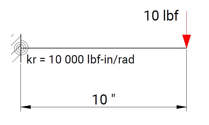
验证模型的几何形状、边界条件和荷载施加情况。
模型参数
| 参数 | 数值 |
|---|---|
| 单元类型 | Beam element |
| 材料 | E = 30 000 ksi |
| 截面属性 | I = 1 000 in⁴ |
| 边界条件 | Left Node – constrain Ux and Uy, Rotational Spring constant about Z-axis kr = 10 000 lbf-in/rad |
| 荷载 | Nodal load −10 lbf |
解析解
Moment at the fixed end due to the tip load:
$$M_1 = P \cdot L$$
Rotation of the fixed end due to the finite spring stiffness:
$$\theta_1 = \frac{M_1}{k_r} = \frac{P \cdot L}{k_r}$$
Deflection at the free end of the cantilever:
$$\delta_2 = \delta_b + \delta_r$$
$$\delta_2 = \frac{P \cdot L^3}{3EI} + \theta_1 \cdot L$$
$$\delta_2 = \frac{P \cdot L^3}{3EI} + \frac{P \cdot L^2}{k_r} = -0.1\ \mathrm{in}$$
Rotation at the free end of the cantilever:
$$\theta_2 = \theta_{b2} + \theta_{r1}$$
$$\theta_2 = \frac{P \cdot L^2}{2EI} + \frac{P \cdot L}{k_r} = -0.01\ \mathrm{rad}$$
数值结果
位移

RodX表格结果

对比
| Parameter | 解析解 | RodX |
|---|---|---|
| Δx(2) | 0.00 | 0.00 |
| Δy(2) | −0.10 | −0.10 |
| θz(2) | −0.01 | −0.01 |
RodX获得的数值结果与解析解吻合。
参考文献
—